|
|
|
Who's Online
There currently are 6043 guests online. |
|
Categories
|
|
Information
|
|
Featured Product
|
|
|
 |
|
|
There are currently no product reviews.
 ;
Simple and fast...
The diagrams are clear and legible; i have been a great help.
The site is very reliable and precise thanks.
 ;
Very easy site. Great service and quick release for download. Manuals are of good quality.
Joop - The Netherlands
;
Very good manual, in depth and complete. Only criticism is that some of the circuit diagrams are slightly blurry and hard to follow for long periods of time, but this is to be expected. Perfect for any maintenance required. Also contains the wiring diagrams of the control cable for constructing extensions.
;
Received a quick response, material was exactly what it was supposed to be. The service did everything I expected it to do. would use service again.
;
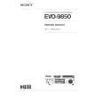
Detailed SONY CFD980 Service Manual at an easy to find one stop shopping. Make my radio hobby technically interesting. Thanks.
â� BLOCK DIAGRAM
ANT 8 8 0 -1 9 1 7 B A M /F M T U N E R O IC 3 0 2 LC 75386 E L E C T R O N IC VO LUM E IC 5 0 1 - 5 0 5 N JM 2060 E Q U A L IZ E R IC 5 0 6 TD A7560 P O W E R IC E N A
B L
FL SP+ RLSP+ FR SP+ RR FL RL FR RR F P SP SP SP SP SP +
P P -2 4 4 9 H -B :N O N F A D E R
G H C D C D M E C H A N IS M LPF IC 2 0 uPD RAD CON 178076G F IO /C D TR O LLER IC 9 0 1 LC 75853 L C D D R IV E R 1 POW ER SU PPLY
I K 1 2 J
TA2157F RF AMP
TC 94A14FA DSP KEY M A T R IX & S W IT C H
NC BA IL L IL L AC NC ON ON
CK UP .C O N T U M IN A T IO N C -S IG N A L IN -S IG N A L O U T
GND
M OTOR D R IV E R BA5983FP
LCD 6 4 5 7 LL+ R+ R-
â� ADJUSTMENT
Item Noise convergence Clock accuracy Procedure 1. Input a 98.1MHz/55dB(1kHz,30% MOD)signal.(0dB=1.4V) 2. Adjust the output to �18±3dB by VR102 when the SSG output is set �20dBμ. 1. Turn off and on the ACC switch,while holding CD EJECT button and POWER button.Repeat it twice slowly. 2. Set a universal timer to TP201,adjust TC201 so that a reading of the meter is 0±0.1 sec/day.
pin 28: NU pin 29: NU : - : Not in use. : - : Not in use. : - : Not in use. : - : Not in use. : - : Analog ground. : IN : Capacitor connection terminal to suppress the ripple. pin 34: VDD 0 pin 35: REG OSC pin 36: X 2 pin 37: X 1 pin 38: GND 0 pin 39: NU pin 40: GND 2 pin 41: AM IF pin 42: FM IF pin 43: VDD PLL pin 44: FM OSC pin 45: AM OSC pin 46: GND PLL pin 47: Voltage Tune pin 48: NU pin 49: IC pin 50: RESET_ pin 51: SP INIT pin 52: NU pin 53: ST_/TWEET_ pin 54: CLK INT pin 55: AUX ON_ pin 56: TEST pin 57: LCD ON_ : - : Positive supply voltage. : IN : Capacitor connection terminal to suppress the ripple. : - : Crystal connection. : - : Crystal connection. : - : Ground. : - : Not in use. : - : Ground. : IN : Input terminal counter for AM : IN : Input terminal counter for FM of the internal universal IF. of the internal universal IF.
Measuring instrument
SSG Milli-volt meter Universal timer
â� EXPLANATION OF IC
052-1173-00 uPD178076GF-541-3BA
1.Terminal Description pin 1: EJECT SW_ pin 2: NU pin pin pin pin pin pin 3: NU 4: VOL DATA 5: VOL CLOCK 6: VOL CE 7: NU 8: LCD DI_
Radio & CD Controller
pin 30: NU pin 31: NU pin 32: A VSS pin 33: REG CPU
: IN : The eject key signal input. : - : Not in use. : - : Not in use. : O : Serial data output to the electric volume IC. : O : Serial data clock output to the electric volume IC. : O : Chip enable signal output to the volume IC. : - : Not in use. : IN : Serial data input from the LCD driver. : O : Serial data output to the LCD driver. : O : Serial data clock output to LCD driver. : O : Chip enable signal output to the LCD driver. : - : Not in use.
pin 9: LCD DO pin 10: LCD CLK pin 11: LCD CE pin 12: NU
pin 13: POWER SW_ : IN : Power switch pulse input. pin 14: VOL 1 : IN : Volume control pulse input from the rotary switch. pin 15: VOL 2 pin 16: ILL_ pin 17: NU pin 18: NU pin 19: NU pin 20: NU pin 21: NU pin 22: NU pin 23: NU pin 24: NU pin 25: NU pin 26: NU pin 27: A VDD : IN : Volume control pulse input from the rotary switch. : IN : Illumination ON signal input. : - : Not in use. : - : Not in use. : - : Not in use. : - : Not in use. : - : Not in use. : - : Not in use. : - : Not in use. : - : Not in use. : - : Not in use. : - : Not in use. : - : Positive supply voltage for the Analog section.
: - : Positive supply voltage for the PLL. : IN : Input terminal of the internal counter for FM OSC( Local Oscillation ). : IN : Input terminal of the internal counter for AM OSC( Local Oscillation ). : - : Ground for the PLL. : O : PLL error output. : - : Not in use. : IN : Not in use. : IN : Reset signal input. : IN : 4SP = "L" , 2SP = "H". : - : Not in use. :I/O: Outputs "L" at AM 900kHz receiving. Inputs "L" at FM stereo receiving. : IN : Without the clock display = "H". : IN : AUX ON signal input. : IN : Test enable signal input. : O : LCD back light ON signal output.
-3-
PP-2449H
|
|
|
> |
|