|
|
|
Who's Online
There currently are 5963 guests and
1 member online. |
|
Categories
|
|
Information
|
|
Featured Product
|
|
|
 |
|
|
There are currently no product reviews.
 ;
Some of the pictures in this manual are a bit irritating. I had to dissassemble the unit and some of the screws have different threads, which is not mentioned in this manual. Also some of the drawings of the boards look different than the actual boards.
After all, the manual was very useful. I was able to recalibrate the capstan drive and it is working fine again.
 ;
This manual is very good. 303 pages scanned in a very high resolution. My camera has bad, leaking capacitors which all of the V5000 models are suffering from these days.
There is a huge part list with all capacitors, transistors etc. in this manual which helped me a lot. Otherwise I would not have been able to buy replacement parts.
The dissassembly guide is very enormous and detailed. Unlike on the Panasonic MS1 manual I downloaded here it actually looks like the real parts look. And the screws are labeled correctly, so you shouldn't have any left after the repair. ;)
;
has all the schematics you could need,and very well laid out format also has all part numbers along with an exploded view which is helpful
;
Very nice to have! Now it is no problem to understand how it is put together.
Helps me a lot.
;
good scans, all is clear. all pages in order. recommended
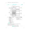
ADJUSTMENT
Item Clock accuracy
SUB
Procedure 1. Connect the Choronometer to TP218. 2. Connect the B/U and ACC line, and Turn on the ACC switch. 3. LCD display change Ver.---, While holding the buttons of MENU,M1,M5 and POWER. 4. Adjust TC201 so that an output of TP218 becomes 0.0 +0.2/-0.0Sec./day. 1. Input the 98.1MHz/55dBu(1kHz 22.5kHz Div.) SSG signal. 2. Set the output to 0dBm(1V)by main volume. 3. Adjust VR102 so that the output level is -18+3/-3dB down when the output of SSG is set to -20dBu. Connect the SSG to Main antenna (Red) side. Set the minimum VR101. Input the 98.1MHz/1kHz 22.5kHz(30%) Div. SSG signal. Input the 26dBu SSG signal and adjust VR101 so that an output of TP101(DIVADJ) becomes High from Low. 5. Confirm that TP101(DIV-ADJ) becomes Low from High within about three seconds of input the 22dBu SSG signal. 6. Confirm that TP101(DIV-ADJ) becomes 10.0V from 2.0V within about one second of input the 30dBu SSG signal. 7. Confirm that TP101(DIV-ADJ) is as follows 1.0V within five seconds of input the 20dBu SSG signal.
RR RH(+) RR RH(-) MUTE BACK UP RR LH(+) RR LH(-) FL FR LH(+) FR AM FR LH(-) RL
Measuring instrument
Choronometer
FM noise convergence
SSG Milli-volt meter
FM DIV.
1. 2. 3. 4.
FR RH(-) STBY
SSG Milli-volt meter Oscilloscope
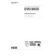
BLOCK DIAGRAM
Main section
J401(POWER/SP) ILLACC GND
IC402 POWER-IC TDA7560
FILLTER ILL CONT. Q415 BEEP Q414,416 Q410 CD-8V ACC-DET S615 CD-EJECT
ILL+
FR RH(+)
ILL
IC501 - 505 EQ-AMP NJM2060V
IC201 IC301 E-VOL LC75412 FM AUDIO-CPU LC723663 VR601 MAIN VOL.
CD
IC103 AM-NC BL101 AM/FM-TUNER AF-OUT OUT
Q408 CD-5V
S601 - 614 KEYMATRICS
IC601 LCD-DRIVER LC75853 1CD MECHANISM LCD601 DISP
ANT101 MAIN
IC102 AF-AMP IC101 FM-DIVER N-IN
SW PWB
PP-2898H-C,F
-4-
|
|
|
> |
|